Difference between revisions of "Watt's linkage"
m |
m |
||
| (7 intermediate revisions by the same user not shown) | |||
| Line 1: | Line 1: | ||
| − | + | {{X}} | |
| − | [[Image:Watts linkage.gif|thumb|Animated depiction of Watt’s linkage]] | + | [[Image:Watts linkage.gif|thumb|454px|Animated depiction of Watt’s linkage]] |
[[Image:Wattslinkage.JPG|thumb|Watt's Linkage]] | [[Image:Wattslinkage.JPG|thumb|Watt's Linkage]] | ||
| + | |||
| + | |||
'''Watt's linkage''' was invented by [[James Watt]] (1736--1819) to constrain the movement of a [[piston]] in a [[steam engine]] to move in a straight line. | '''Watt's linkage''' was invented by [[James Watt]] (1736--1819) to constrain the movement of a [[piston]] in a [[steam engine]] to move in a straight line. | ||
| Line 25: | Line 27: | ||
{{Automobile configurations}} | {{Automobile configurations}} | ||
| + | {{Piston engine configurations}} | ||
| + | {{Machine configurations|state=uncollapsed}} | ||
| + | |||
[[Category:Automotive suspension technologies]] | [[Category:Automotive suspension technologies]] | ||
[[Category:Linkages]] | [[Category:Linkages]] | ||
Latest revision as of 08:31, 7 October 2009
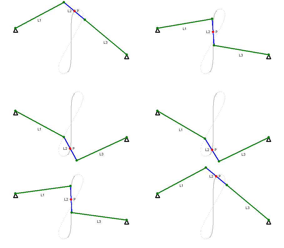
Watt's linkage was invented by James Watt (1736--1819) to constrain the movement of a piston in a steam engine to move in a straight line.
The idea of its genesis using links is contained in a letter he wrote to Matthew Boulton in June 1784.
- I have got a glimpse of a method of causing a piston rod to move up and down perpendicularly by only fixing it to a piece of iron upon the beam, without chains or perpendicular guides [...] and one of the most ingenious simple pieces of mechanics I have invented.
This linkage does not generate a true straight line motion, and indeed Watt did not claim it did so. In a letter to Boulton on 11th September 1784 he describes the linkage as follows.
- The convexities of the arches, lying in contrary directions, there is a certain point in the connecting-lever, which has very little sensible variation from a straight line.
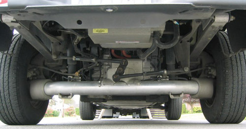
The Watt's linkage is also an automotive rear suspension designed in the early twentieth century as an improvement over the Panhard rod as a means of locating a rear beam axle of an automobile relative to the body and preventing relative movement side to side. Whereas the Panhard rod is pivoted at both axle and body forcing the axle to move in an arc, thus introducing a sideways component into the vertical movement of the axle, the Watt's linkage ensures pure vertical motion.
It consists of two almost symmetrically arranged long rods mounted one at each side of the chassis and running parallel to and behind the rear axle, where they attach to the ends of a short vertical bar whose center is mounted to the center of the axle and which is free to rotate in the plane at right angles to the automobile's longitudinal dimension. As in the Panhard rod, the sideways arms themselves are free to pivot vertically at either end. Thus, each sideways member acts as a shorter Panhard rod mounted to the center vertical member providing lateral location. In contrast to the Panhard rod's action, however, the sideways components of the motion of the two arms as they pivot around their outboard mountings cancel each other in their effect on the axle and are instead taken up by the center member's rotation about its axis.

It should be noted that the Watt's linkage is not limited in use as an improved version of a Panhard rod. Many rearend racing suspension systems also use the Watt's linkage to locate the rear axle from front to rear. This application usually requires 2 Watt's linkages, one on the driver's side and one on the passenger's side. Suspension binding during deflection is prevented by floating the center linkage around the axle instead of welding it directly to the axle. Some means of preventing the read axle from rotating is then needed which is a form of "caster" control. Often times only one side is "floated" which eliminates the axle rotation issue.
External link
| Piston engine configurations | |
|---|---|
| Straight | Single, 2, 3, 4, 5, 6, 8, 9, 10, 12, 14 |
| V | 2, 4, 5, 6, 8, 10, 12, 16, 20, 24 |
| Flat | 2, 4, 6, 8, 10, 12, 16, H |
| W | 8, 9, 12, 16, 18 |
| Other inline | H, VR, Opposed, U (Square), X |
| Other | Hemi, Radial, Rotary, Pistonless, Deltic, (Wankel) |
| Heat engines | |
|---|---|
| Stroke cycles One • Two • Four • Six • | |
| Engine types Gas turbine • Piston • Jet • Rocket engine • Steam engine • Stirling engine • Tschudi• Twingle Rotary • Wankel • Free-piston • Britalus • Coomber • Swing-piston • Orbital • Quasiturbine | |
| Valves Cylinder head porting • D slide • Four-stroke • Manifold • Multi • Piston • Poppet • Sleeve | |
| Piston layouts Single cylinder • Straight • Opposed • Flat • V • W • H • Deltic • Radial • Rocket engine nozzle • Rotary • Stelzer • Controlled Combustion • Bourke | |
| Motion mechanisms Cam • Connecting rod • Coomber rotary • Crank • Crank substitute • Crankshaft • Linkages (Evans • Peaucellier-Lipkin • Sector straight-line • Watt) • Double acting/differential cylinder | |
| Thermodynamic cycle |
