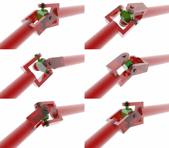
Universal joint
A universal joint, U joint, Cardan joint, or Hardy-Spicer, Hooke's joint is a joint in a rigid rod that allows the rod to 'bend' in any direction. It consists of a pair of ordinary hinges located close together, but oriented at 90° relative to each other.
History
The concept of the universal joint is based on the design of gimbals, which have been in use since antiquity. One anticipation of the universal joint was its use by the Ancient Greeks on ballistae. The first person known to have suggested its use for transmitting motive power was Gerolamo Cardano, an Italian mathematician, in 1545, although it is unclear whether he produced a working model. Christopher Polhem later reinvented it and it was called "Polhem knot". In Europe, the device is often called the Cardan joint or Cardan shaft. Robert Hooke produced a working universal joint in 1676, giving rise to an alternative name, the Hooke's joint. It was the American car manufacturer Henry Ford who gave it the name universal joint.
Application
Universal joints are common wherever a driveshaft needs to turn a corner; a driveshaft with a universal joint can freely rotate through the universal joint, and no gears are required to couple the two ends. The most obvious example of this application of a universal joint is in the driveshafts of automobiles, a technology known as the Hotchkiss drive.
Angular speed

|

|
| Angular output shaft speed ω2 for different angles β of the input shaft | Output shaft angle for different angles β of the input shaft |
However, when the two shafts are at an angle other than 180° (straight), the driven shaft does not rotate with constant angular speed in relation to the drive shaft; the more the angle goes toward 90° the jerkier the movement gets (clearly, when the angle β = 90° the shafts would even lock). However, the overall average speed of the driven shaft remains the same as that of driving shaft, and so speed ratio of the driven to the driving shaft on average is 1:1 over multiple rotations.
The angular speed ω2 of the driven shaft, as a function of the angular speed of the driving shaft ω1 and the angle of the driving shaft φ1, is found using:
- <math>\omega_2 = \frac{\omega_1\cos\beta}{1-\sin^2\beta\sin^2\phi_1}</math>
and the angular acceleration,
- <math>\alpha_2 = \frac{\omega_1^2\sin^2\beta\cos\beta\sin 2\phi_1}{(1-\sin^2\beta\sin^2\phi_1)^2}</math>
To prevent the jerky rotation of the axle or driven shaft there usually are two U-joints in a three part shaft assembly. The second U-joint will convert the jerky movement back to an even, uniform speed of the third shaft - if both the driving and the driven shaft are parallel and the two universal joints are correctly aligned with each other. Usually β <= 45°.
CV joint
Another way to prevent jerky movement is to use a constant-velocity joint (CV joint) or 'homokinetic' joint ('homo' meaning 'same', 'kinetic' meaning 'movement' or motion). A homokinetic joint has the same function as a U joint but is constructed with a cage and steel balls moving in grooves, inside a 'dome' (see picture).
- driveshaft from the transmission,
- steel balls (in this case 6) in a 'cage'. The balls run in grooves in the dome.
- cage, splined to the driveshaft
- spherical 'dome' and outer driveshaft, part of the hub of the wheel.
For a CV joint ω2 = ω1 for any angle β.
A new design of constant velocity joint, the Thompson coupling, is a development of two universal joints assembled coaxially.
See also
References
- Theory of Machines 3 from National University of Ireland

