Universal joint
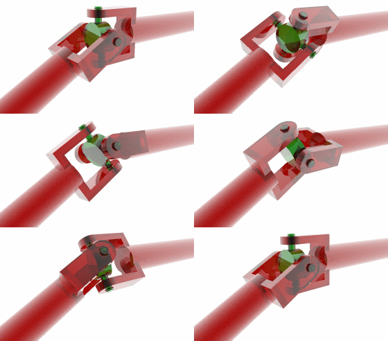
A universal joint, U joint, Cardan joint, or Hardy-Spicer, Hooke's joint is a joint in a rigid rod that allows the rod to 'bend' in any direction. It consists of a pair of ordinary hinges located close together, but oriented at 90° relative to each other.
History
The concept of the universal joint is based on the design of gimbals, which have been in use since antiquity. One anticipation of the universal joint was its use by the Ancient Greeks on ballistae. The first person known to have suggested its use for transmitting motive power was Gerolamo Cardano, an Italian mathematician, in 1545, although it is unclear whether he produced a working model. Christopher Polhem later reinvented it and it was called "Polhem knot". In Europe, the device is often called the Cardan joint or Cardan shaft. Robert Hooke produced a working universal joint in 1676, giving rise to an alternative name, the Hooke's joint. It was the American car manufacturer Henry Ford who gave it the name universal joint.
Application
Universal joints are common wherever a driveshaft needs to turn a corner; a driveshaft with a universal joint can freely rotate through the universal joint, and no gears are required to couple the two ends. The most obvious example of this application of a universal joint is in the driveshafts of automobiles, a technology known as the Hotchkiss drive.
Equation of motion

The Cardan joint suffers from one major problem: even when the drive shaft rotates at a constant speed, the driven shaft rotates at a variable speed, thus causing vibration and wear. The variation in the speed of the driven shaft depends on the configuration of the joint, which is specified by three variables:
- <math>\gamma_1</math> The angle of rotation of axle 1
- <math>\gamma_2</math> The angle of rotation of axle 2
- <math>\beta</math> The angle of the axles with respect to each other, zero being parallel, or straight through.
These variables are illustrated in the diagram on the right. Also shown are a set of fixed coordinate axes with unit vectors <math>\hat{\mathbf{x}}</math> and <math>\hat{\mathbf{y}}</math> and the planes of rotation of each axle. These planes of rotation are perpendicular to the axes of rotation and do not move as the axles rotate. The two axles are joined by a gimbal which is not shown. However, axle 1 attaches to the gimbal at the red points on the red plane of rotation in the diagram, and axle 2 attaches at the blue points on the blue plane. Coordinate systems fixed with respect to the rotating axles are defined as having their x-axis unit vectors (<math>\hat{\mathbf{x}}_1</math> and <math>\hat{\mathbf{x}}_2</math>) pointing from the origin towards one of the connection points. As shown in the diagram, <math>\hat{\mathbf{x}}_1</math> is at angle <math>\gamma_1</math> with respect to its beginning position along the x axis and <math>\hat{\mathbf{x}}_2</math> is at angle <math>\gamma_2</math> with respect to its beginning position along the y axis.
<math>\hat{\mathbf{x}}_1</math> is confined to the "red plane" in the diagram and is related to <math>\gamma_1</math> by:
- <math>
\hat{\mathbf{x}}_1=[\cos\gamma_1\,,\,\sin\gamma_1\,,\,0] </math>
<math>\hat{\mathbf{x}}_2</math> is confined to the "blue plane" in the diagram and is the result of the unit vector on the x axis <math>\hat{x}=[1,0,0]</math> being rotated through Euler angles <math>[\pi\!/2\,,\,\beta\,,\,\gamma_2</math>]:
- <math>
\hat{\mathbf{x}}_2 = [-\cos\beta\sin\gamma_2\,,\,\cos\gamma_2\,,\,\sin\beta\sin\gamma_2] </math>
A constraint on the <math>\hat{\mathbf{x}}_1</math> and <math>\hat{\mathbf{x}}_2</math> vectors is that since they are fixed in the gimbal, they must remain at right angles to each other:
- <math>
\hat{\mathbf{x}}_1 \cdot \hat{\mathbf{x}}_2 = 0 </math>
Thus the equation of motion relating the two angular positions is given by:
- <math>
\sin\gamma_1\cos\gamma_2=\cos\beta\cos\gamma_1\sin\gamma_2\, </math>
The angles <math>\gamma_1</math> and <math>\gamma_2</math> in a rotating joint will be functions of time. Differentiating the equation of motion with respect to time and using the equation of motion itself to eliminate a variable yields the relationship between the angular velocities <math>\omega_1=d\gamma_1/dt</math> and <math>\omega_2=d\gamma_2/dt</math>:

|

|
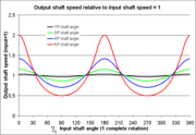
| Angular output shaft speed <math>\omega_2\,</math> for different angles <math>\beta\,</math> of the input shaft | Output shaft angle for different angles <math>\beta\,</math> of the input shaft |
- <math>
\omega_2=\frac{\omega_1\cos\beta}{1-\sin^2\beta\sin^2\gamma_1} </math>
As shown in the plots, the angular velocities are not linearly related, but rather are periodic with a period twice that of the rotating shafts. The angular velocity equation can again be differentiated to get the relation between the angular accelerations <math>a_1</math> and <math>a_2</math>:
- <math>
a_2 = \frac{a_1 \cos\beta }{1-\sin^2\beta\,\cos^2\gamma_1}-\frac{\omega_1^2\cos\beta\sin^2\beta\sin 2\gamma_1}{(1-\sin^2\beta\cos^2\gamma_1)^2} </math>
See also
References
- Theory of Machines 3 from National University of Ireland

